


My doorbell rings. That is what doorbells do. When it rings, it is mostly annoying, unless it is the pizza guy delivering a pizza. Some people ring the doorbell for several seconds or press it a couple of times, thinking that it makes people answer the door quicker. I just find it annoying. A simple solution would be to turn off the doorbell by installing a switch but for me that is way too simple; moreover you could forget switching the doorbell on again. Doorbells on the market that can be switched off or play a nice melody are vastly overpriced. Very often these are also wireless doorbells, leaving the wired system unused, which means that you have to give up the old doorbell, which is unlike the wireless one, maintenance free.
In my most creative moment I thought about creating a controllable doorbell with logging facility. The doorbell would ring briefly even if somebody presses it for 2 seconds, it should be silent at given hours and any doorbell button press would be logged into a database. Also the doorbell could ring on other sorts of activity, for instance when somebody wants to Skype you, when an email arrives or something else that’s important.
The answer to it is Arduino. The Arduino UNO that I have is ideal for this task. My last (and first) Arduino project was to pick up the DCF77 signal and get the time from the atomic clock. Basically the DCF77 signal is not necessary for the project, but the shield that I created for it has some room left which can be used to connect the doorbell switch and another peripheral like a piezo speaker. The piezo speaker will be nice for testing purposes. To really make this work the schematics of the current doorbell needs to be studied, I just looked for schematics on the Internet.
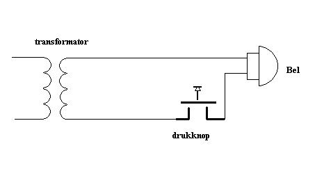
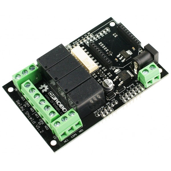
The doorbell is connected to a power supply providing 8 Volts AC to the doorbell. In order control the doorbell separately from the doorbell switch the circuit has to be changed. Where now the doorbell switch is, the Arduino should be placed. A second circuit with the Arduino and the doorbell switch has to be created as well. The Arduino cannot handle AC power, also the current is around 1A, this is nothing for the senstive PINs of Transistor-transistor logic! The DFRobot relay shield seems to be able to do this task. It has four relays, so actually a little bit overkill.
So now we have a little shopping list:
- Arduino UNO (or another version, but this is the minimum)
- Arduino Ethernet shield
- DFRobot relay shield
- DFRobot prototype shield, with DCF77 logic connected (not really required, but part of my existing project)
- Piezo speaker (not really required)
The DCF77 is connected to pin 2, this is nice because we can attach an interrupt to it, which simplifies the code. Another interrupt can be attached to pin 3, so it seems good to connect the doorbell switch to that pin 3. The other boards also require some PINs and this leads to some interesting conflicts!
- PIN 0 – unused
- PIN 1 – unused
- PIN 2 – relay shield, relay #1 & DCF77
- PIN 3 – relay shield, relay #2 & Doorbell switch
- PIN 4 – relay shield, relay #3 & Ethernet shield, SS MicroSD
- PIN 5 – relay shield, relay #4
- PIN 6 – unused
- PIN 7 – unused
- PIN 8 – unused
- PIN 9 – Piezo speaker
- PIN 10 – Ethernet shield, SS Ethernet
- PIN 11 – Ethernet shield, MOSI
- PIN 12 – Ethernet shield, MISO
- PIN 13 – Ethernet shield, SCK
PIN 2 to PIN 5 are being used by the relay shield but also the DCF77 antenna, the doorbell switch and the Ethernet shield. So it would make sense that the relay shield moves out of the way. I found the “go between” shield that allows remapping of pins:
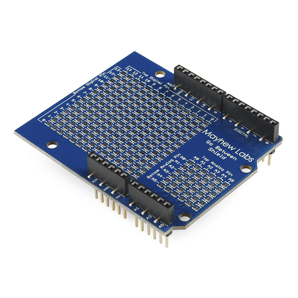
I wanted relay #1 to be on PIN 5, relay #2 on PIN6, relay #3 on PIN7 and relay #4 on PIN8. After configuring it the shield looked like this:
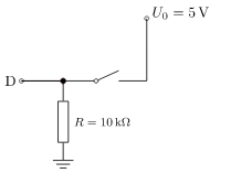
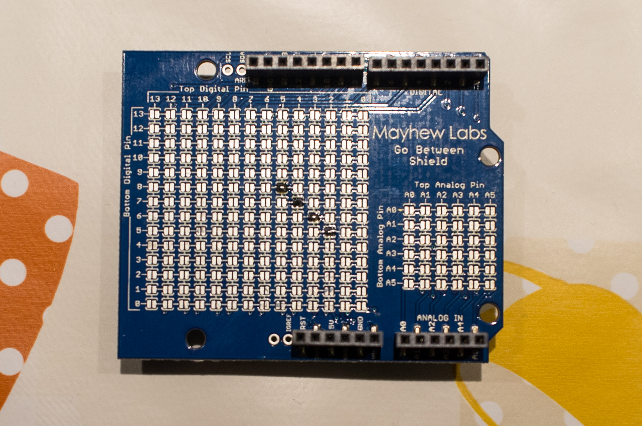 The only thing that now matters is the order of how the shield are stacked. The relay shield is on top, straight after the “go between” shield and after that either the Ethernet shield or the DCF77/piezo/doorbell switch shield. Hardware wise we are almost there, I attached a pull down resistor of 10K between PIN 3 and GND, the doorbell switch is placed between +5V and PIN3. The purpose of the pull down resistor is that in case the doorbell switch is open the remaining current or noise is burned and no tri-state occurs. Tri-state means that the state of the PIN 3 would be floating and the Arduino would not be able to determine the right state (which is 0).
Now we are ready to rock and roll. This bit of code proofs the concept:
/******************************************
* Doorbell project
*
* $Revision: 3 $:
* $Author: hans $:
* $LastChangedDate: 2013-01-29 10:10:18 +0100 (Tue, 29 Jan 2013) $:
*
******************************************/
#define DOORBELL_PIN 3
#define DOORBELL_INT 1 //only UNO and MEGA2560
#define RELAY1_PIN 5
#define RELAY2_PIN 6
#define RELAY3_PIN 7
#define RELAY4_PIN 8
#define PIEZO_PIN 9
void setup()
{
Serial.begin(57600);
Serial.println("Doorbell application");
attachInterrupt(DOORBELL_INT, ring, RISING);
}
void loop()
{
}
void ring()
{
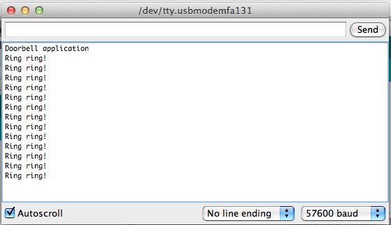
Serial.println("Ring ring!");
}
Now when I press the doorbell I can monitor the serial monitor and see something happening!
During this first test I noticed that sometimes pressing the doorbell switch caused the interrupt routine to be called twice, this is because one may press the switch halfway or it is caused by dust / debris in the switch. The ‘noise’ can be filtered with a small capacitor in parallel with the switch, but I decided to resolve this in software. I came up with the following solution, which also prevents multiple rings when people are impatient. The DOORBELL_TIME define is 5000, which means 5000 milliseconds, so the doorbell is only allowed to ring once every 5 seconds. the interrupt service routine is now called intDoorbell (before it was declared as ring).
update: I also noticed phantom doorbell interrupts, the doorbell would ring when nobody pressed the doorbell switch. It happened when somebody was touching metal in the proximity of the doorbell-switch or when somebody was switching on the light in house. To prevent this I added a delay of 50ms in the interrupt service and read the digital pin again. if it is not high anymore nobody pressed the doorbell and this was just a spike. This is called debounce, here you find an article about it. A hardware solution is on the way.
  #define RELAY_DOORBELL 5
  #define DOORBELL_TIME 5000   // Minimal 5 seconds between the rings
  unsigned char handle_ring = 0;

 /******************************************
  * interrupt handler when somebody presses
  * the doorbell switch
  ******************************************/
 void intDoorbell()
 {
  byte doorbellValue;
  unsigned long current_time = millis();
  static unsigned long last_time = 0;

  delay(50);

  doorbellValue=digitalRead(DOORBELL_PIN);

  // test whether the last doorbell press was long enough ago
  if ((doorbellValue) && (current_time - last_time >= DOORBELL_TIME))
  {
    handle_ring = 1;
    last_time = current_time;
  }
 }
I declared a global variable handle_ring, the variable indicates that somebody pressed the switch, but only when meeting the criteria that a given time have passed since the last time the doorbell was pressed. It is good practice to keep interrupt service routines as short as possible, so business as usual can continue. the handle_ring variable is now handled (and cleared) by the loop() function.
 void loop()
 {
  if (handle_ring)
  {
   Serial.println("Ring ring!");
   handle_ring = 0;

   for (int i=0; i<2; i++)
   {
    bitWrite(PORTD,5,1);
    delay(50);
    bitWrite(PORTD,5,0);
    delay(100);
   }
  }
 }
Although my doorbell rings now for only a split second (300 milliseconds), the project is not finished. Next is to install the Ethernet shield and communicate to my database on my NAS that somebody rang the doorbell. Please continue to follow this blog updates will be made… keep on reading in part 2 (Ethernetshield, logging in SQL and multitasking telnet service implementation)
Oh before i forget, I bought my Arduino hardware at iprototype.nl and floris.cc. The DCF77 receiver I bought via Conrad. Special thanks to Frans Goddijn for some editorial work!