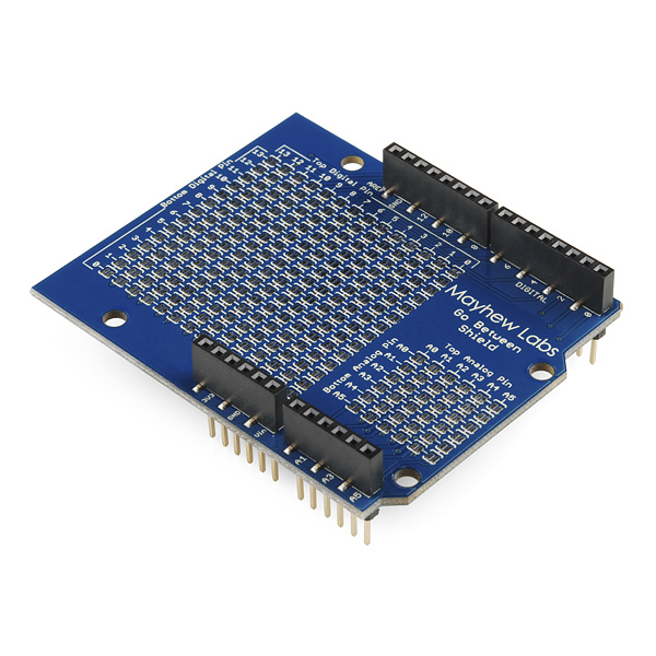
After the basic functionality has been implemented (see my previous post about the doorbell project), the next step of the doorbell project is to implement the Ethernet shield TCP/IP functionality with some extra features, such as NTP time synchronization, logging of doorbell events in an SQL server and a telnet service that allows to control the doorbell. One could for instance think about an API that makes the doorbell ring for incoming Skype calls.

Soon I will show you the source code for the doorbell project on my Arduino with the integration of the Ethernet shield. You will see that I gave up using the DCF77 hardware (for now) and use NTP time synchronisation instead. At this moment the time is not really necessary, but at a later stage I want to add functionality for quiet hours where the doorbell will not ring. I also decided to make the doorbell project more than just a doorbell. The doorbell can now ring in different patterns, indicating different type of events, i.e. when an email arrives or when something else happens that deserves some priority. To realize this the Arduino needs to be approachable for instance in the form of a TCP service. In this blog I will explain about
- The Ethernet shield and TCP/IP integration
- The NTP service and what one needs to keep in mnd
- Logging the doorbell event into an external database
- A telnet TCP service for handling external events that make the doorbell ring (in a different pattern)
- Simple multitasking
TCP/IP: To get the Ethernet shield to work is real simple, first a few includes are required:
 #include <SPI.h>
 #include <Ethernet.h>
 #include <EthernetUdp.h>
Now we need to set up TCP/IP, this has to happen only once, so it is part of setup
 void setup()
 {
  // Enter a MAC address for your controller below.
  // Newer Ethernet shields have a MAC address printed on a sticker on the shield
  byte mac[] = {
   0x90, 0xA2, 0xDA, 0x01, 0x01, 0x01  };

  IPAddress ip(192,168,2,202);
  unsigned int localPort = 8888;   // local port to listen for UDP packets

  // IP & UDP settings
  Ethernet.begin(mac, ip);  // Set MAC and IP address, netmask is default 255.255.255.0
}
The Wiznet chip on the Ethernet shield is a pretty nice chip, it does a lot automatically for us. The only thing we have to do is set up the MAC address, you can make up something like in the example or you can find a MAC address on the label on the shield. Furthermore in my example I chose to have a static IP address. DHCP is real easy too: just call Ethernet.begin(mac), so without ip-argument.
NTP: This code is readily available as an example in the Arduino IDE, but need to be changed a little. We basically don’t want to bother about the time synchronisation and let it happen automatically. Arduino offers this functionality via SetSyncProvider and SetSyncInterval functions. SetSyncProvider requires an argument that points to a function that returns the time in unix format (the seconds that have passed since 1 Jan 1970). SetSyncInterval requires an argument the number of seconds between each call to the sync provider function. From the NTP sample code I took parts of the code.
 #define NTP_PACKET_SIZE 48      // NTP time stamp is in the first 48 bytes of the message
 byte packetBuffer[ NTP_PACKET_SIZE]; // buffer to hold incoming and outgoing packets

 /******************************************
  * send an NTP request to the time server
  * at the given address
  ******************************************/
 unsigned long sendNTPpacket(IPAddress& address)
 {
  Serial.print("Sending NTP packet to ");
  for (byte thisByte = 0; thisByte < 4; thisByte++) {
   // print the value of each byte of the IP address:
   Serial.print(address[thisByte], DEC);
   Serial.print(".");
  }
  Serial.println();

  // set all bytes in the buffer to 0
  memset(packetBuffer, 0, NTP_PACKET_SIZE);
  // Initialize values needed to form NTP request
  // (see URL above for details on the packets)
  packetBuffer[0] = 0b11100011;  // LI, Version, Mode
  packetBuffer[1] = 0;   // Stratum, or type of clock
  packetBuffer[2] = 6;   // Polling Interval
  packetBuffer[3] = 0xEC; // Peer Clock Precision
  // 8 bytes of zero for Root Delay & Root Dispersion
  packetBuffer[12] = 49;
  packetBuffer[13] = 0x4E;
  packetBuffer[14] = 49;
  packetBuffer[15] = 52;

  // all NTP fields have been given values, now
  // you can send a packet requesting a timestamp:
  Udp.beginPacket(address, 123); //NTP requests are to port 123
  Udp.write(packetBuffer,NTP_PACKET_SIZE);
  Udp.endPacket();
 }

 /******************************************
  * get the NTP time
  ******************************************/
 unsigned long getNTPtime()
 {
  Serial.println("Time synchronization starting");
  IPAddress timeServer(64,147,116,229); // time.nist.gov NTP server
  sendNTPpacket(timeServer); // send an NTP packet to a time server
  delay(1000);
  if ( Udp.parsePacket() ) {
   // We've received a packet, read the data from it
   Udp.read(packetBuffer,NTP_PACKET_SIZE); // read the packet into the buffer

   //the timestamp starts at byte 40 of the received packet and is four bytes,
   // or two words, long. First, esxtract the two words:

   unsigned long highWord = word(packetBuffer[40], packetBuffer[41]);
   unsigned long lowWord = word(packetBuffer[42], packetBuffer[43]);
   // combine the four bytes (two words) into a long integer
   // this is NTP time (seconds since Jan 1 1900):
   unsigned long secsSince1900 = highWord << 16 | lowWord;
   Serial.print("Seconds since Jan 1 1900 = " );
   Serial.println(secsSince1900);

   // now convert NTP time into everyday time:
   Serial.print("Unix time = ");
   // Unix time starts on Jan 1 1970. In seconds, that's 2208988800:
   const unsigned long seventyYears = 2208988800UL;
   // subtract seventy years:
   unsigned long epoch = secsSince1900 - seventyYears;

   //add correction for GMT+1
   epoch = epoch + 3600;
   //todo daylight saving time

   // print Unix time:
   Serial.println(epoch);
   return epoch;
  }
  return 0;
 }
The code is split into two functions, the function that is used as sync provider is getNTPtime. I believe the code is not too robust, also something is missing here. which is the correction for daylight savings time. But for now this is fine. In the setup function it is now possible to add two calls, after the IP address has been set up:
  // setup time synchronization, this is a call to the function that contacts the teim server
  // synchronize time every 7200 seconds (2 hours)
  setSyncProvider(getNTPtime);
  setSyncInterval(7200);
Note that 7200 (2 hours) is adjustable to anything you desire.
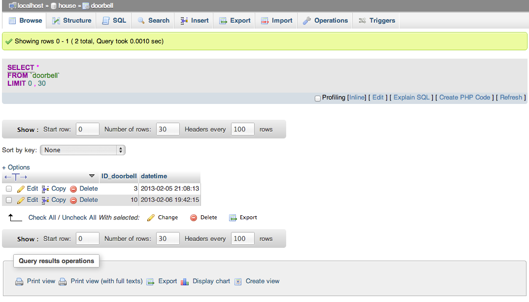
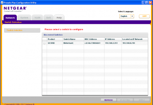
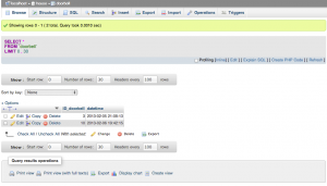
Logging: Now that we have TCP/IP set up logging is fairly easy, especially from the Arduino side. At my home I have a NAS from Synology. Pretty much out of the box you can run a Webserver with PHP and MySQL. A PHP-file is a script that is runs on the Webserver when somebody makes a request to the PHP-file. The PHP script usually does a couple of things in the background and produced HTML-code. In our case the script will connect to the MySQL database and make an entry to a table that captures doorbell events. The design of the SQL table is simple, it has two fields: a primary key (unique identifier) and a timestamp which records the time of the event.
I won’t go in much more details now since this is a blog about Arduino, but if you need help, I am happy to assist. From the Arduino site I only need to request a php file via the hypertext transfer protocol (HTTP). In your browser this would be the line HTTP://192.168.2.100/doring.php where 192.168.2.100 is the IP address of my NAS. The typical Arduino code would be:
 /******************************************
  * make a request to a webpage on the NAS
  * so the NAS can log a database entry
  ******************************************/
 void doWeblog() {
  // Initialize the Ethernet client library
  // with the IP address and port of the server
  // that you want to connect to (port 80 is default for HTTP):
  EthernetClient client;

  if (client.connect(webServer, 80)) {
   Serial.println("connected");
   // Make a HTTP request:
   client.println("GET /doring.php HTTP/1.0");
   client.println();
   if (client.available()) {
    char c = client.read();
    Serial.print(c);
   }
   // if the server's disconnected, stop the client:
   if (!client.connected()) {
    Serial.println();
    Serial.println("disconnecting.");

   }
   client.stop();
  }
 }
Note: I have not tested this function for robustness, but it worked just fine.
External events handling / multitasking: This is probably the most exciting part, because there are some nice challenges here. Our doorbell has now quite some extra functionality, and we are going to add one more, a telnet TCP service that can receive requests to make the doorbell ring. Implementation of this idea requires some new ideas: most of the time the Arduino will have nothing to do and if there is something to do it is mostly just a single task. It can handle a single task pretty well, but imagine a situation where an external event is triggered and somebody is opening a telnet connection. The regular code that you would use would probably involve a while loop that is waiting for characters, causing that other events will be blocked. That’s said this is a single tasking service. Let’s have a look to the simplified code as found in the Arduino Webserver example, this code is part of loop():
1:   EthernetClient client = server.available();
2:   if (client) {
3:
4:    while (client.connected()) {
5:     if (client.available()) {
6:      char c = client.read();
7:
8:      }
9:     }
10:   }
With this code a newly connected client is served pretty well, and as you see the code will loop until data is received. Receiving data is usually just a matter of a split second, but theoretically can be much longer and nothing else can happen in between (except for Interrupts and probably the time synchronization). If I’d implement this code and open a telnet session to the Arduino it would appear if the board is hanging! The answer to the solution is simple, but requires a different design:
Avoid time consuming loops (while) and delays (delay) in loop(), use if and millis() so you can do other things in between.
But how will we handle loops then you might think. Well that’s fairly easy when you consider that the loop() function is a loop in it self. so imagine about a project that involves two LED’s (with resistors) connected to analog ports of the Arduino board. without using for or a while loop you can fade them seperately.
 int i, j;

 void setup()
 {
  pinMode(3,OUTPUT);
  pinMode(5,OUTPUT);
  i=0;
  j=128;
 }

 void loop()
 {
  analogWrite(3,i);
  analogWrite(5,j);

  i = (i + 1) % 256;
  j = (j + 1) % 256;
  delay(10);
 }
This code handles two tasks at the same time, in a single cycle it sends a new value to each LED and increments the value that is send to the LEDs for the next cycle. This is in essence a multitasking program!
Back to the doorbell project, the idea is that a telnet service is available on the Arduino board. the Arduino would greet you with a welcome message and you could start typing a sequence of rings and pauses that you want to be played by the doorbell. The Arduino would check the sequence and reply with an acknowledgement or a negative acknowledgement. When acknowledged the doorbell would start right away playing the pattern.
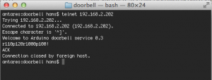
Below you find the code to this multitasking service. In the code you will see that I defined different states that can be reached, to make this primitive multitasking as fair as possible I ordered the states in the reverse order. This means that in one cycle only one new state of the telnet TCP service is handled (except for the situation when the user disconnects). Note that this code makes use of only the piezo speaker for the telnet service, else it drives people mad in the house. I use SVN for version control, soon this blog will be updated and you can checkout the code from there.
/******************************************
* Doorbell project
*
* $Revision: 12 $:
* $Author: hans $:
* $LastChangedDate: 2013-02-10 13:56:18 +0100 (Sun, 10 Feb 2013) $:
*
******************************************/
#include <Time.h>
#include <SPI.h>
#include <Ethernet.h>
#include <EthernetUdp.h>
#define DOORBELL_PIN 3
#define DOORBELL_INT 1 // only UNO and MEGA2560
#define DOORBELL_TIME 5000 // Minimal 5 seconds between the rings
#define RELAY1_PIN 5
#define RELAY_DOORBELL 5
#define RELAY2_PIN 6
#define RELAY3_PIN 7
#define RELAY4_PIN 8
#define PIEZO_PIN 9
#define NTP_PACKET_SIZE 48 // NTP time stamp is in the first 48 bytes of the message
#define STATE_DISCONNECTED 0
#define STATE_AVAILABLE 1
#define STATE_CONNECTED 2
#define STATE_DATAAVAIL 3
#define APP_VERSION "0.3"
boolean ring_doorbell = false;
// Initialize the Ethernet server library
// with the IP address and port you want to use
// (port 23 is default for telnet):
EthernetServer server(23);
EthernetUDP Udp; // A UDP instance to let us send and receive packets over UDP
byte packetBuffer[ NTP_PACKET_SIZE]; // buffer to hold incoming and outgoing packets
IPAddress webServer(192,168,2,100); // The IP address of my NAS
EthernetClient telnetClient; // telnetClient that will be connected
String message = "";
String buzz_pattern = "";
void setup()
{
// Enter a MAC address for your controller below.
// Newer Ethernet shields have a MAC address printed on a sticker on the shield
byte mac[] = {
0x90, 0xA2, 0xDA, 0x0D, 0xC2, 0x93 };
IPAddress ip(192,168,2,202);
unsigned int localPort = 8888; // local port to listen for UDP packets
// Enable serial communication for debugging
Serial.begin(57600);
Serial.print("Arduino doorbell service v");
Serial.println(APP_VERSION);
// IP & UDP settings
Ethernet.begin(mac, ip); // Set MAC and IP address, netmask is default 255.255.255.0
Udp.begin(localPort); // local port to listen for UDP packets
// setup time synchronization, this is a call to the function that contacts the teim server
// synchronize time every 7200 seconds (2 hours)
setSyncProvider(getNTPtime);
setSyncInterval(7200);
// Attach interrupt for PIN 3. On rising edge interrupt service routine intDoorbell is called
attachInterrupt(DOORBELL_INT, intDoorbell, RISING);
// Set Piezo PIN to output mode
pinMode(PIEZO_PIN, OUTPUT);
// Set Doorbell relay to output mode
pinMode(RELAY_DOORBELL, OUTPUT);
//digitalWrite(9,HIGH);
analogWrite(PIEZO_PIN, 20); // Almost any value can be used except 0 and 255
delay(650); // wait for a delayms ms
//digitalWrite(9,LOW);
analogWrite(PIEZO_PIN, 0); // 0 turns it off
}
void loop()
{
static byte srv_state = STATE_DISCONNECTED;
static unsigned int count = 0;
static unsigned int piezo_delay, doorbell_delay;
static boolean finish_ring = 0;
unsigned int cur_time = millis();
// Check whether ring_doorbell is set. typically it is set by the intDoorbell function that is called
// when the doorbell button is pressed.
if (ring_doorbell)
{
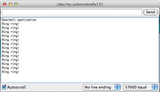
Serial.println("Doorbell button pressed - ring ring!");
ring_doorbell = false; // clear the ring_doorbell
ctlDoorbell(true); // start to ring the doorbell
doorbell_delay=cur_time + 100; // calculate the time till when the doorbell has to ring
finish_ring = true; // indicate that the doorbell has to be stopped after delay has been reached
logDoorbell(); // log to the webserver
if (buzz_pattern==""); // if the piezo is not performing a buzz
buzz_pattern="r50p100r50p100"; // insert a new buzz_pattern
}
// check whether the doorbell is still ringing and the time has reached to switch it of again
if ((doorbell_delay<=cur_time) && (finish_ring))
{
ctlDoorbell(false); // stop the doorbell
finish_ring = false; // finish, the doorbell doesn't need to be stopped now anymore
}
// check whether a new tone has to be processed
if ((piezo_delay<=cur_time) && (buzz_pattern!=""))
{
ctlPiezo(procTone()); // process the tone (r for ring, p for pause)
piezo_delay = cur_time + procDelay();
// calculate the time for the delay given in the buzz pattern
}
// Telnet stage 4.
// data is available!
if (srv_state==STATE_DATAAVAIL) // reaching this state means data is available
{
message = checkMsg(); // check if received message is valid
if ((message!="") && (buzz_pattern=="")) {
// the message is not empty & no other buzz_pattern is in use
buzz_pattern = message; // the new buzz_pattern is install
telnetClient.println("ACK"); // Acknowledge to the telnetClient
Serial.print("Telnet - Message acknowledged, ring pattern: ");
Serial.println(buzz_pattern);
ctlPiezo(procTone()); // start immediately processing the pattern
piezo_delay= cur_time + procDelay();
// calculate the time for the delay given in the buzz pattern
}
else
{
telnetClient.println("NAK"); // negative acknowledgement, invalid message or another buzz pattern is ongoing
Serial.println("Telnet - Message discarded");
Serial.print(message);
}
message = ""; // the buzz_pattern is installed or discarded, anyway, clear the message
telnetClient.stop(); // and disconnect the telnetClient
srv_state = STATE_DISCONNECTED; // set the appropriate state.
}
// Telnet stage 3.
// check if data is available
if (srv_state==STATE_CONNECTED)
{
if (!telnetClient.connected())
{
srv_state=STATE_DISCONNECTED; // Was the connection dropped intermediate?
message=""; // clear the message (cleanup)
telnetClient.stop(); // stop the telnetClient (cleanup)
Serial.println("Telnet - Stage 3 telnetClient disconnected");
}
else
{
if (telnetClient.available())
{
//data available
char c = telnetClient.read(); // read the character that is available
message = message + c; // add to the existing message
}
else
{
if (message!="") // no more data available and the message is not empty
srv_state=STATE_DATAAVAIL; // so a new state has been reached
}
}
}
// Telnet stage 2.
// check if a telnetClient connection is connected and say hello
if (srv_state==STATE_AVAILABLE)
{
if (telnetClient.connected())
{
srv_state=STATE_CONNECTED; // update the server state
telnetClient.print("Welcome to Arduino doorbell service ");
telnetClient.println(APP_VERSION); // send the welcome message
telnetClient.flush(); // flush any data that is received too early
Serial.println("Telnet - Stage 2 telnetClient connected");
}
else
srv_state=STATE_DISCONNECTED;
}
// Telnet stage 1.
// create a telnetClient object
if (srv_state==STATE_DISCONNECTED)
{
srv_state=STATE_AVAILABLE;
telnetClient = server.available();
}
}
/******************************************
* interrupt handler when somebody presses
* the doorbell switch
******************************************/
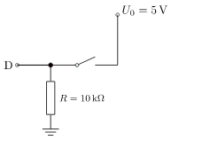
void intDoorbell()
{
byte doorbellValue;
unsigned long current_time = millis();
static unsigned long last_time = 0;
// wait 50ms and read the pin. if it is still high then this is not a spike
delay(50);
doorbellValue=digitalRead(DOORBELL_PIN);
// test whether the last doorbell press was long enough ago
if ((doorbellValue) && (current_time - last_time >= DOORBELL_TIME))
{
ring_doorbell = true;
last_time = current_time;
}
}
/******************************************
* Ring the doorbell
* rings the bell and buzz the piezo speaker
******************************************/
void ctlDoorbell(boolean state)
{
bitWrite(PORTD,RELAY_DOORBELL,state);
}
/******************************************
* Buzz the piezo
* rings the bell and buzz the piezo speaker
******************************************/
void ctlPiezo(boolean state){
//digitalWrite(PIEZO_PIN, state);
if (state) {
analogWrite(PIEZO_PIN,20);
return;
}
analogWrite(PIEZO_PIN,0);
return;
}
/******************************************
* Read the tone (ring or pause)
* and remove it from the buzz pattern
******************************************/
boolean procTone()
{
char tone = buzz_pattern[0];
buzz_pattern = buzz_pattern.substring(1, buzz_pattern.length());
if (tone=='r')
return true;
return false;
}
/******************************************
* Read the delay
* and remove it from the buzz pattern
******************************************/
unsigned int procDelay()
{
unsigned int ipause;
char pause[6];
byte i;
for (i=1; i<5; i++) {
if ((buzz_pattern[i]=='r') || (buzz_pattern[i]=='p'))
break;
}
buzz_pattern.toCharArray(pause,i+1);
ipause = atoi((char *)&pause);
buzz_pattern = buzz_pattern.substring(i, buzz_pattern.length());
return ipause;
}
/******************************************
* make a request to a webpage on the NAS
* so the NAS can log a database entry
******************************************/
void logDoorbell() {
// Initialize the Ethernet telnetClient library
// with the IP address and port of the server
// that you want to connect to (port 80 is default for HTTP):
EthernetClient webClient;
if (webClient.connect(webServer, 80)) {
Serial.println("connected to Logserver");
// Make a HTTP request:
webClient.println("GET /doring.php HTTP/1.0");
webClient.println();
if (webClient.available()) {
char c = webClient.read();
Serial.print(c);
}
// if the server's disconnected, stop the telnetClient:
if (!webClient.connected()) {
Serial.println();
Serial.println("disconnecting.");
}
webClient.stop();
}
}
/******************************************
* send an NTP request to the time server
* at the given address
******************************************/
unsigned long sendNTPpacket(IPAddress& address)
{
Serial.print("Sending NTP packet to ");
for (byte thisByte = 0; thisByte < 4; thisByte++) {
// print the value of each byte of the IP address:
Serial.print(address[thisByte], DEC);
Serial.print(".");
}
Serial.println();
// set all bytes in the buffer to 0
memset(packetBuffer, 0, NTP_PACKET_SIZE);
// Initialize values needed to form NTP request
// (see URL above for details on the packets)
packetBuffer[0] = 0b11100011; // LI, Version, Mode
packetBuffer[1] = 0; // Stratum, or type of clock
packetBuffer[2] = 6; // Polling Interval
packetBuffer[3] = 0xEC; // Peer Clock Precision
// 8 bytes of zero for Root Delay & Root Dispersion
packetBuffer[12] = 49;
packetBuffer[13] = 0x4E;
packetBuffer[14] = 49;
packetBuffer[15] = 52;
// all NTP fields have been given values, now
// you can send a packet requesting a timestamp:
Udp.beginPacket(address, 123); //NTP requests are to port 123
Udp.write(packetBuffer,NTP_PACKET_SIZE);
Udp.endPacket();
}
/******************************************
* get the NTP time
******************************************/
unsigned long getNTPtime()
{
Serial.println("Time synchronization starting");
IPAddress timeServer(64,147,116,229); // time.nist.gov NTP server
sendNTPpacket(timeServer); // send an NTP packet to a time server
delay(1000);
if ( Udp.parsePacket() ) {
// We've received a packet, read the data from it
Udp.read(packetBuffer,NTP_PACKET_SIZE); // read the packet into the buffer
//the timestamp starts at byte 40 of the received packet and is four bytes,
// or two words, long. First, esxtract the two words:
unsigned long highWord = word(packetBuffer[40], packetBuffer[41]);
unsigned long lowWord = word(packetBuffer[42], packetBuffer[43]);
// combine the four bytes (two words) into a long integer
// this is NTP time (seconds since Jan 1 1900):
unsigned long secsSince1900 = highWord << 16 | lowWord;
Serial.print("Seconds since Jan 1 1900 = " );
Serial.println(secsSince1900);
// now convert NTP time into everyday time:
Serial.print("Unix time = ");
// Unix time starts on Jan 1 1970. In seconds, that's 2208988800:
const unsigned long seventyYears = 2208988800UL;
// subtract seventy years:
unsigned long epoch = secsSince1900 - seventyYears;
//add correction for GMT+1
epoch = epoch + 3600;
//todo daylight saving time
// print Unix time:
Serial.println(epoch);
return epoch;
}
return 0;
}
String checkMsg() {
String retstring = "";
if (message.length()>2)
{
for (int i=0; i<message.length(); i++) {
if (message[i]=='!')
{
//retval = true;
retstring = message.substring(0,i);
break;
}
if ((message[i]!='p') && (message[i]!='r') && ((message[i]<'0') || (message[i]>'9')))
break;
}
}
return retstring;
}
I use SVN for version control. you can checkout the code soon from there.